Transmission gratings
Transmission gratings and how to use them
Generally most amateurs start with the 1.25" filter sized transmission gratings - Star Analyser, SA 100 or SA 200. These can be used in front of a camera lens "Objective grating" or with the telescope optics "In the converging beam". They can also be used to make DIY spectrographs (with or without an entrance slit). Other sized gratings are available from Paton Hawksley and Edmund Optics which can be DIY mounted to cameras and telescopes.
A grating produces bright "zero order" images of the target stars with two (or more) spectra, one on each side of the zero order. One will appear much brighter than the other, this is the "blazed 1st order" spectrum and is the one you want to image. Position the target first order image over to one side of the frame with the bright 1st order spectrum close to mid frame. If the spectrum to too long to fit across the picture frame, you need to reduce the spacing between the grating and the camera chip.
The TransSpec spreadsheet (right click, "download as") allows you to calculate the spectrum size and possible resolution based on your parameters.
There's an on-line Calculator for the Star Analyser gratings.
Objective grating
Using the objective grating is as simple as mounting the grating on front of the camera lens. You can either modify a lens cover to hold the grating securely, or purchase a suitable adaptor which holds the grating and screws onto the front of the camera lens.
Make sure the grating is aligned to present a spectral image horizontally across the chip.
Using a DSLR is very popular, this should be set to ISO>200 and the exposure will depend on whether the camera is mounted on a fixed tripod (Try exposures up to 30 sec) or on a driven/ tracking equatorial mount.
Some good results have been achieved with a Canon 85mm prime lens and an "Astrotrac" platform. The resolution obtained with a suitable objective grating is usually higher than when the grating is used "in the converging beam" on a telescope.
Uwe Zurmahl has achieved some excellent results with his objective grating set-ups. Details here.
In the converging beam
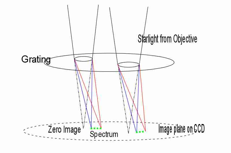
When the grating is mounted in a telescope, usually at some short distance (30 to 100mm) in front of a camera/ CCD at prime focus it is an "In the converging beam" arrangement. The light from the target, focused by the telescope objective goes through the grating, disperses to a spectrum and continues to the focus on the camera. The amount of "spread" of the spectral image depends on - the number of lines in the grating (l/mm) and the distance between the grating and the camera chip.
Make sure the grating is aligned to present a spectral image horizontally across the chip.
The grating can be mounted in a 1.25" nosepiece and connected to the camera using a T2 adaptor or mounted in a filter wheel/ filter slide in front of your CCD.
Once again the TransSpec spreadsheet (right click, "download as") allows you to calculate the spectrum size and possible resolution based on your input parameters.

Focus the telescope normally on the target star and then replace the eyepiece with the grating/ camera combo. Take a couple of exposures to ensure the zero order star image and the 1st order blazed spectrum (brightest spectrum) are framed in the field of view, with the spectrum horizontal across the frame.
Re-focus on the spectrum, NOT the zero order star...... look for a narrow spectral band and some obvious dark lines in the spectrum. Your image acquisition software should have a "profile" function where you can quickly review the intensities along the spectral image. Change the exposure as necessary to achieve a high ADU value ( check the histogram) in the spectral peak. Don't worry about the zero order being over saturated! Once it has produced the spectrum it has no further impact on the outcome.
Using other gratings
Paton Hawksley and ThorLabs also produce usable non filter sized transmission gratings. These are usually square or rectangular and need some DIY skills to make suitable holders. They can be used as objective gratings or in the converging beam.
Other transmission grating concepts
To improve the resolution and reduce sky background, a slit can be added to a grating. This is discussed and illustrated in "Astronomical Spectroscopy for Amateurs", p 184
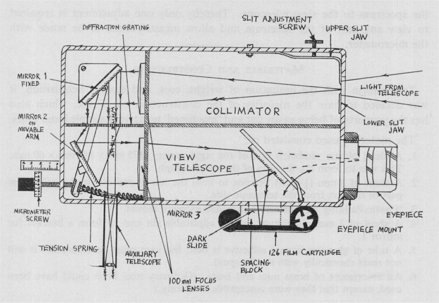
A simple transmission grating slit spectrograph is the Watkis design. The educational type gratings can be utilised very easily.
Buil's LORIS design based on a 300 l/mm grating and a couple of camera lenses is a straight forward build.
The CAOS guys have a neat design - TRAGOS which uses a 200 l/mm grating and a 11 degree Carpenter grism in a collimated beam arrangement.
Carpenter Prisms (Grisms)
In 1963 Edwin Carpenter of the Steward Observatory advocated the use of a secondary prism mounted immediately in front of the grating. This wedge prism presented a square surface to the incoming beam and the included angle of the prism was calculated to provide a deviation angle to effectively bring the dispersed beam from the grating back close to the optical axis. This significantly reduced the chromatic coma aberrations.
The improvement is minimal on 100 l/mm gratings but when used on >200 l/mm gratings can give good results.
Some interesting information on transmission gratings is given in this link.